Tuesday, July 9, 2013

Wheel house door

I built the wheel house door out of Aluminum. Given how exposed the wheel house is, I thought Aluminum would offer me a more tough door. Now that it's all said and done, I do think the aluminum door is more robust than my wooden salon door. The salon door, at two inches thick is for sure a tough door, but the all welded Aluminum door appears to be pretty tough given the weight of it.

The first decision I had to make on the wheel house door build was how to build the frame.  I found a piece of 2 x 6 x 1/4 " angle at the scrap yard and ripped the six inch side to 4" to match my 4" wheel house frame depth. The angles on the rough opening are a degree off of 90, so a little fitting had to be done before I could tack the frame together. I guess at this point I should say that I TIG welded the wheel house door. The frame was assembled using miter's, with all the cuts being made with my miter saw... you gotta love Aluminum. Once the frame was fit in to the opening, I built the actual door frame using some 1" x 2" angle and some 2" flat bar for internal framing. I had the hinges in the shop, so figuring out the reveal of the door was not too big of a deal. With hindsight being 20/20, I wish I had used a hinge that did not require a mortise. I ended up having to create a  mortise for the hinge in the door, and while not  a deal killer for the success of the job, it was sort of a pain.

The flat bar cross member framing of the door was laid out for a couple of strategic reasons. Two of the cross members were laid out as to house the Trioving lock assembly. To make all the lock assembly housing hidden yet removable, I added an internal plate to bolt the lock assembly in to. Trioving bores four holes through this composite lock assembly housing for just the purpose I needed. The four bores are the same size needed to tap a 1/4-20 thread so one can attach the lock housing assembly to the door. On my wooden salon door, I created a mortise, then epoxied the lock assembly housing in to the mortise. The other two flat bar cross members were installed in the locations where my inside door dogs will be bolted to the interior door skin. In order to keep the door skin flat, I had to weld a few braces in to the door frame perpendicular to the cross members.

Aluminum is great material to work with, but controlling movement due to the immense heat created by TIG welding is a challenge. Taking your time and paying attention to the  heat is crucial. I also found that by clamping blocks of heavy stainless steel under my welds and along side of weld areas helped the heat sink in to the blocks and keep things under control. My external door skin was .090.

Because I had always intended on painting the door, I ground all the welds on the exterior of the door and on the frame. Once I had the welds ground flush, and repaired a few welds that failed as a result of grinding, I sand blasted the door and frame. On As per advice from my paint vendor, I conditioned the aluminum with some material I applied with a spray bottle.  The conditioner had to sit on the metal for 15 or 20  minutes, then I hosed the metal clean and let it drip dry. My paint guy said the conditioner is good for 24 for hours, so after baking in the sun for a few hours, I hung the door from some lines and gave it two coats of epoxy primer along with the frame. After priming the door, I faired the ground edge of the door first using West epoxy mixed with fairing compound, then finished with Rage filler sanded to 320 grit. Spot painting two coats of primer on the filler to seal it, then three or four coats of acrylic urethane top coat and the door was ready for assembly.

I pre drilled the frame for 1/4" screws, and will not final install the door until the super structure is landed at the launch site later this summer. I also have only installed a temporary stop as I'm still undecided on what type of gasket I"m going to use to seal the door to the stop. Once I decide on the type of gasket and how much room the gasket requires, I'll bolt the door stop to the frame. The door stop will be  hardwood and will extend out the the edge of the door frame to also catch the interior  finish wall sheathing. Another important build part of my wheel house door is that I decided that the interior skin of the door will be Cherry to match the wheel house finish wood. Because the doors interior skin will be plywood, I bolted firing to the cross members.

After I land the super structure to the hull and have all he weld zones painted, I'm going to have the spray foam insulators back to spray all those areas. When the spray contractor is on site, I'm going to have him spray foam the inside of the door before I install the plywood interior skin.

Now that the wheel house door is complete along with the salon door, the last piece of being able to secure the boat from weather and other undesirables  is  now complete. I've pretty much stopped working on finish type things of the build, and am now focusing on getting things ready to move her out of the barn. Getting her in the water next Spring is the plan, and believe it or not, that date is fast approaching. It's time to it done.

I started to add some You tube videos if anyone's interested. The videos are pretty lame, but hopefully I'll start improving on them. I'll post a link soon.


 Cheers

Friday, May 31, 2013

Salon passage door completion

I'm calling the salon passage door a wrap and the little work that needs to be done to it will be finished once it's hung for good in it's opening. I did hang it to work out some of the details and to make sure the lock set had no issues. The door is temporarily hung, and will be removed for the trip to the launch site just like all the other case work I've done in the super structure.


Once the stainless hinges were in the shop I built a jig to route the mortise's . The jig assures perfect alignment between of the  hinges between the door and the door jamb. The jig is just 1/2 plywood with the hinge layout cut in the jig a  1/6" of an inch larger the the hinge itself. The router is fitted with a guide bushing and a 1/2" mortising bit.

The door jambs were cut 1/8" wider than the opening. Experience has taught me the having the door jambs a bit proud of the finished wall surfaces make casing the door much more trouble free. Because the aft wall is only two inches thick, I decided to make the stop the door closes against the full width of the jamb. I also made the stop a full 3/4" thick vs the 5/8 one would normally see on a door  in a house. The door stop now is the full width of the jamb so the casing will cover the joint  between the  jamb and the stop. I might regret this one day, but I glued and nailed the stop to the jamb, and once it's permanently hung in the opening I"ll add screws to the stop. A few of the screws will be thru bolted to the metal frames as will some of the hinge screws and the stainless keeper that the lock set lands in to.

One of the reasons I hung the door was to see how the door  seal gasket was going to work out. I purchased a 3/8 round hollow rubber gasket with a 3/4" spline on it. My intent was to  cut a rabbet in the stop for the spline to lay in, and have the 3/8" round hollow  bulb act as the seal getting compressed when the door closed against the stop. Fitting this idea up proved to be a problem, and after a day of tinkering with it, I decided to used a closed cell gasket. I had some 1/8 and 1/4 x 3/4 closed cell foam in the shop and was able to position the stop so that the 1/8 material would work and create a nice seal. Watching the door close on my mocked  up pieces had all looking good and I'm happy it looks like that idea will work out OK.


Before I was able to call the door a finished  job, I wanted to make sure the Trioving lock set was going to work given the thicker stops I installed. I've seen situations before where full mortised lock sets have the  handles hitting the stop as the door opens. Trioving uses a very deep mortise for the lock set @ 4 1/4" so this scenario really wasn't a problem. Trioving has some pretty nice user friendly design in their gear. The screws they use to hold the sets together are machined to adjust. Once you have the lock set in place, you cut the screws in a machined groove they  have to get the proper length. This way one does not have to use a die to repair the cut end. Another nice detail Trioving uses is how they hold he handles on to the square stock that passes through the lock set. The square stock is split in half for a certain distance where the handle lands, and the set screw that holds the handle in place is extra  long. The  extra long set screw has a long nipple machined on the end of it and as you tighten the set screw in place,  it engages the slot in the square stock and spreads it out creating an interference fit between the square stock and the handle. This is a much nicer way in my opinion to retain the  handle vs a set screw that just engages the stock.

I purchased the Trioving lock sets off of Ebay used, and the keepers that mortise in to the door jamb did not come with the lock sets. I used some scrap 3/16  316 stainless I have in the barn to fabricate the keeper. I used the  mill to  machine the slots that the two lock set bolts will engage. The bolts are 1/2" wide, so I machined the slots to 9/16". Once the door is hung for good at the launch site, and after the seal is in place, I'll adjust the keeper in the jamb and final grind the slots depending on how tight I want the door to  close.  I might have to TIG weld a small return piece of stock on the slot that engages the handle bolt, but I'll figure that out once the door is permanently hung. I I also might try to broach square corners in the keeper, but once again, well see how it fits.
 

Now that the salon passage door is complete, I'm thinking of turning my attentions to the wheel house aluminum door. I was thinking of making it a dutch style, but given how tall my bulwark is, I"m not so sure I n need to do that. I have pretty good ventilation in the wheelhouse, and if I'm in a situation where I need to have the door closed, 100% closed vs 50% closed with a dutch door is not going to make any difference regarding ventilation. The dutch door seems to be  more appropriate for boats without the bulwark, and also adds some complexity to the fabricating. I'm still up in the air on that decision so we'll see.

Cheers


Monday, May 20, 2013

Salon passage door

There are two passage door on board, one in the salon and another in the wheel house. The salon door I decided to build out of wood, and the wheel house door will be aluminum. The salon passage door is on the aft deck, under the aft  deck roof and protected by the 36" solid steel bulwark that surrounds the aft deck. The wheel house door is a little more exposed given that it's on the front of the boat. The free board on the at the wheel house door part of the boat is almost 8', and the wheel house is protected by a 46" tall steel Portuguese Bridge. The fore deck is also protected by a 36" tall solid steel bulwark.

The wooden salon passage door is what I would describe as robust. Because I am using Trioving mortised lock sets, and because I wanted a stout door I decided to  build the door 2" thick. The panel for the door is 3/4" plywood. The door is built out of Cherry.

I did not have any 2" thick cherry stock so I had to laminate three pieces together to get my 2" thickness. I like to laminate material using a form, and welding a couple of 4" H beams together made for a nice straight form that was easy to clamp to. By using a "straight as string" form, my lamination's came off of the form perfectly straight.

In my opinion, mortise and tenon joinery is best for a door such as this. The first step in joining the door together after I had all the stock prepped was to plow the groove for the panel. I used a stacked dado cutter in the table say to plow a 3/4" x 3/4" groove stopping short of style ends by 1". I finished the panel dado with a cutter set up in my mill. I then used the same cutter in the mill to cut the mortises to their 2 1/4" depth. The mill is really a nice way to cut these deep mortises.


The tenons were cut using the same stack dado cutter in the table saw. Because of the amount of time to laminate the stock I was very cautious cutting the tenons and left them about .030 over sized, and  then used a chisel and sand paper to bring them to the final thickness. The fit I was looking for was for hand pressure only to drive the parts together. A slight interference fit with  not mallet needed. There is such a thing as too tight. Dry fitting the parts together found no problems. Once the door was glued, clamped and squared, I through pinned the mortises using 3/8" walnut dowels. The Cherry has plenty of character and is for sure nice to look at, but the walnut pegs add a wee bit more interest to the door.

The mortise for the Trioving lock set was cut on the mill using a 1 3/8 forstener bit.  I'll go in to the lock sets a little more in the next post, but I will say that I found the lock sets used on Ebay two years ago. If any one knows anything about Trioving, you probably know it's high priced stuff. I had to take one lock set apart to test fit it in the door, and I was impressed by the high quality of the parts, and the fact that it's all easy to service and re build-able.  Nice equipment.

I sanded the door to 220 grit and coated with three coats of urethane. The next step will be to mortise the stainless steel  hinges, build the jambs, and devise the gasket. I feel pretty confident I can make the door weather tight and able to handle some water getting on to the aft deck. I think I'm going to fabricate two dogs for it similar to how I dealt with the bulwark doors.

Cheers


Wednesday, May 8, 2013

Porch ceiling, soffit, and some wiring

Historically speaking, this is always a bad time of year for me. Work is back with a vengeance, but funds have yet to start flowing back my way. I'm almost booked up for the rest of the year, and everyone I know that does my type of work is for sure not complaining about the amount of work out there. Because cash flow is not working so well right now, I've had to start using material I've purchased last summer to keep things moving forward.

My latest project has been getting the aft deck ceiling installed, installing the salon soffit, the port, starboard, and aft steaming navigation lights, the aft deck ceiling lights, along with the salon soffit lights. I also wired the salon ceiling for lights as I intend to install the ceiling in the salon before we head to the launch site.

The aft deck ceiling was built using BC plywood which I painted. Because I wanted to be able to remove the ceiling with not to much trouble, I used stainless screws with finish washers to fasten the ceiling. Instead of hiding the joints in the ceiling, I covered them with battens pinned in place with some stainless brads. Because I have so much Cherry lumber in the barn, I made the battens out of Cherry and left the bright with a few coats of urethane. We'll see how the bright battens suit us against the painted ceiling. 

Every light on the boat is LED. Last summer I purchased 40, seven watt 12 volt can lights. I purchased direct from factory in China, and have to say I'm pleased with the quality of the light. The lights are aluminum with an aluminum heat sink. All the machining is top notch, and the penetrations from the wiring are epoxy sealed along with having the wiring tinned. I purchased 40 lights so I could get to a certain discount level, but I also wanted to have spares on board for replacements. I checked every light when they showed up and every light did what it was supposed to do. To date, I have about seven lights working on board now, and I'm totally impressed with how bright they are, how cool they stay, and how much electricity they don't use.

For lighting the aft deck ceiling, I installed two of the seven watt can lights. Because of how the ceiling is framed, I can easily add another light using a fish tape in the future, but I doubt I'll need it as the two lights I have installed give plenty of light.

I installed a LED work light on the aft deck to illuminate the swim platform. I will also have two work lights in the mast along with one more work light on the bill of the wheel house. The work light for the swim platform is switched from inside the salon door.

The salon soffit overhangs the salon walls about six inches. I decided to install a one watt LED light over each of the three windows. These lights are blue, and my intent was for accent. I think the lights will look pretty sharp while we're at anchor or at a harbor.

I do  have a design complaint regarding the aft deck ceiling. The trim piece of metal that makes up the salon soffit is about 4" tall. As the trim turns to wrap around the aft deck ceiling, it gets reduced in height to about 3". I don't know why this happens and it could be a flaw in the cut file. I saw this and knew it was going to be an issue when I was framing the super structure but I chose to do nothing about it. What this caused me to do was force the plywood ceiling up at the rear of the aft deck so that the plywood still remained above the drip edge of the trim  piece. The plywood ceiling has a  subtle curve upwards over it's last 18" aft.  Not only does the plywood need to be above the drip edge, it needs to be above it about 3/8" in order to keep the reveal constant around the aft deck ceiling. The other big issue of having the plywood protected by the trim piece is to keep roof water from rolling around and getting to the edge of the plywood. It really did not look that  noticeable until I installed the cherry battens. I can tell you it's a big job to fix and I doubt I"m going to fix it. It really doesn't bother me that much.  

There is really no reason why I can't install ( other than lack of funds) the ceiling in the salon now. Because it's going to go much faster while in the shop, I went ahead and made all the preparations to install the ceiling. The first thing I did regarding this was to make sure all the timber frames were installed to catch the bead boards that will make the ceiling. Once the framing was complete, I located all the lights and light switch locations. The basic layout is that as one enters the salon door, you'll turn on six can lights from a switch by the door. Another switch in the galley will turn on three lights; one above the sink, one above the range, and another above the fridge. There will be another light in the half  bath.

Since I was wiring the ceilings, I decided to go ahead and run the wiring  feeding the switches, and also installed a switch for the aft deck work light, the aft deck ceiling light, and the salon ceiling lights. The soffit lights will be switched from the wheel house and the feed has not been established.

The wheel house will also be switched from a wall, but I want to have some red lights in there along with a few of my already purchased can lights. So given that, I'll probably have two switches for the wheel house ceiling lights. 

All my wiring connections were made using heat shrink crimp type connectors. For larger connections where more than two wires joined, I used potted wire nuts. Some purists might frown on a potted wire nut in a marine environment, but I have 100% confidence in them. I've been using potted wire nuts for assembling splice boxes in septic tanks and sewage lift stations for 25 years. I have yet to see corrosion in those wire nuts be and issue and I can assure you that ocean air is no where near as corrosive as the inside of a septic tank. Potted wire  nuts are pricey, but you get what you pay for and they're worth the money.

My immediate goal is to complete the salon ceiling, and build the salon door. I  have to be able to lock the boat up once at the launch site, so a proper salon door is a must. The salon door is going to be wood, and the wheel house door is going to be aluminum.

A large piece of wiring and carpentry has now been checked off of my list. Having good reliable lighting is a must and it feels good to have this part of the project working and off the list. Once the boat is at the launch site, the soffit I just finished will be about 16' in the air, and since I have  no side decks I would have had to use scaffold  to do this work. It was a good thing to be able to quickly do it in the shop while it was only 7' off the ground. 

Cheers

Sunday, April 7, 2013

A little progress

Spring is here for sure and I do have a little progress to report. I've not made as much headway as I would have like to in the last few weeks, but like the song says, a  little bit is better than nada.

I think I've taken the salon as far as I can in regards to building cabinets and furniture. The latest project completed was fabricating the end caps for the dinette benches, and a small table that will sit between the two comfy chairs we will have. I think the small table will house  the am/fm stereo for the salon, and has a drawer for stashing the remote control for the TV. The end caps for the bench, while  not a job, required a bit of time. Because of the 16" width, the end caps needed to be glued up. I had to decide  how I wanted to have the bench seat riser connect to the end cap and chose a dado which had to be plowed in to the end cap. I did not want to see end grain wood on the end caps, so I fabricated a cap that had a dado plowed in to it so it could slip over the top of the end cap. While I was building the end caps for the salon dinette, I also did the same thing for the wheel house bench seating.


I took a look at doing some work in the wheel house, but felt that it is going to be better waiting until the super structure is landed on the hull in a few months. The wheel house floor has a decent camber to it, and also falls off grade forward to aft. I don't think the super structure is going to rack when we lift it, but I'm not 100% sure it won't, and there's no point fastening any finish ply to the front of the wheel house if there's a chance it could move. I did figure out the camber of the wheel  house floor, and fabricated the face frame for the bench seat drawer unit. I gave myself plenty of room to scribe the face frame to the floor and still have an inch of face frame left on the bottom once it was fit. Because I not had the face frame built, I had the drawer size in front of me, so I decided to build the three drawers that will go in the assembly.  The far port side opening in the face frame is for the air conditioner vent that supplies the wheel house.

Because I could possibly be drilling holes in the wheel house face frame and the four end caps for the bench seats, I did not put any finish on these parts. All these little odds and ends parts I"m making will make assembly at the launch site go much more quickly .


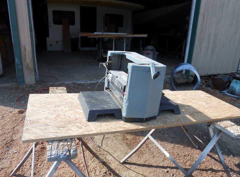
For the last four or five years, I've been threatening myself to go and buy a real planer to build this boat. The current planer I  have is a  15 year old Delta 12" thickness planer that is really undersized for how much lumber I'm running through it. I really need a 15", 240 volt machine with a three knife cutter  head. The Delta machine has seen better days, but seems to still get the job done. Having sharp knives in the machine is the only way the it has a fighting chance of keeping up with what I ask it to do. When I first bought the machine, I had a local sharpening guy do the knife sharpening work for me. The problem I had with the professional sharpening is that the blades seemed to dull quickly. The edge they produced, while sharp, did not have enough meat on the back side, so the cutting edge would fail, then dull, and begin to leave ridges on the work. As long as the knives do not have a severe nick in them, I prefer to sharpen them myself. To sharpen my jointer and planer knives, I use a jig cut in to a piece of hardwood to  hold the knife at the correct angle. The sharpening media I use is 300 grit, 2" wide adhesive sand paper wrapped around a hard wood block. Before I put the knife in the holding jig, I flatten the back of he knife using the 300 grit block. With the blades held firmly at the correct angle and the jig clamped in the vise, not much time is needed to revive the edge.  Once the edge looks good and all the shiny spots have been taken off of the edge, I'll hone it with the same block using 600 grit self adhesive paper. Sharp tools are one of my pet peeves, and having them makes the work much more enjoyable and consistent.

I still have a long list of things I want to get finished before I move her out of the barn namely: Aft deck ceiling including ceiling lights, rear steamer light, rear work lights. Paint aft deck ceiling. Pull ceiling light wiring in salon and wheel house and locate switch's. Water line from salon sink to salon 1/2 bath. Salon and wheel house doors.  Hydraulic lines from engine room to anchor winch. Hydraulic lines from engine room to bow thruster. Hydraulic reservoir install. Weld vent in salon roof for gray water holding tank that I forgot. One more coat of urethane and caulk undersides of bulwark cap. Weld "D" rings to  hull to chain hull down to dolly. This is pretty  much my punch list, and I'm going to try to stick to it before she leaves the barn. Hopefully, the list won't grow to much larger and I'll have her ready to move by early Summer or late Spring. The boat yard I'm bringing her to is packed full right now but after the first of May, it will begin to clear out.

Cheers


Thursday, March 7, 2013

Dinette


Winter is hanging on to our part of the world and the paying work I have going on or scheduled has been halted.  This makes things good for working on the boat but not so good for paying bills. My guilt level stays low as I'm able to get work done on the boat with lumber that cost me next to nothing. All the lumber I"m using on the interior was harvested from my acreage and milled over a year ago. This is the only way I can afford to do this since Cherry lumber in my part of the world is selling for $7.00 per board foot.

With the galley now finished I've turned my attention to the dinette. The dinette is on the port side between the galley and the aft bulkhead. The dinette table will collapse down and convert to a double berth. The double berth will be about 6'3' long and 44" wide.

I raised the dinette platform off of the salon floor eight inches. Eight inches is right on the border on being an uncomfortable step regarding height. The platform was raised so that the space under the platform could be used for drawers, and a chase for the duct work feeding the salon and the wheel house. The bench's for the dinette will also double as lockers for the boat's life jackets. The port side fuel fill and vent connections will also happen under the dinette bench seat.

The plywood seats you see are not the finished seats rather they are framing grade plywood I used to mock up the area. I started with rule of thumb measurements to see how things felt, and planned on adjusting as I went. The only adjustment I made was to angle the bench seat riser inward two inches to give ones feet more room. That two inches makes a huge difference in how comfortable the seats feel. Until the boat build, I've never been one to mock t hings up, but to tell you the truth, mocking things up has been pretty useful. Before I committed to cutting the dinette table, I wanted to make sure everything worked and felt good.  The finished elevation of the seats is 17" above the platform and the width of the seat is 16". We're planning on seat cushions, so I'm going to lower the seat two inches to compensate for the foam. As you move forward, the boat gets wider so the dinette seats follow this flare as does the dinette table.

The only real bug in the dinette was the collapsible table support. I went with a commercially made pedestal that is a half way decent unit. The problem was that the pedestal is that the stanchion finishes out 6" below the deck  when the table is collapsed down. In order to make that work, I had to alter the center drawer. I kicked it around for a few days and decided the best fix was to header off the back of the drawer to allow the stanchion to slip passed it. By simply re shaping the drawer, I did not  have to mess with the glides, the drawer unit bulkhead, and the drawer unit framing. I was also able to keep the table pedestal in the  center of the dinette, which was important for stability. It was a easy solution that no one will notice.


Most of the finish wood in the salon is Cherry. I had been digging through my stash of Walnut when building the island for the  house, and came across two boards that were 1 1/2" thick x 10" wide. They were choice old growth Walnut with almost no sapwood. The boards were jointed straight, and edged glued with #2 biscuits for reinforcing. Personally, I think biscuits add a lot of strength to this joint, and are quick and easy to install.The Walnut boards have been sticker ed in the loft for about 12 years, and because they were old growth and flat when dried, they required minimal planing, and I was able to get a finished thickness of 1 3/8". On the last boat we owned, the dinette table was cut square and was a fuzz uncomfortable in regard to  how close the table edge was to the seat edge. I decided to curve three sides of the table in two inches to give one some relief, and also give the top a little interest. Now that it's all said and done, I like the curve, but I could have made it less slight... say about an inch. I'll have to do something in the seat riser for the top to land on for creating the berth. Since I was giving the table some interest with the curves, I decided to take it a little further and  inlay a band of Tiger Maple around the edge. The Tiger Maple band is 1/4" wide x 3/16 deep. The Tiger maple is bright white, and helps breaks up the size of the top. I was also going to inlay in a compass rose in the center of the top, but decided I had done enough and wanted to avoid making things look busy. I might do a compass rose in the wheel house table. The pictures really don't do the top much justice as the contrast between the Maple and Walnut is pretty choice. What really makes it interesting is the brilliant white radial bands of the Tiger maple and how it pops with the gloss finish. It's a pretty piece. Deciding how to treat the table edge had me thinking on it for a day or two. I had the choice of lightly easing the edge with sanding, leaving the edge sharp, or rounding it over with the router. I decided to round it over with a 3/8 bit, and am  happy with how it feels and looks. Because the top is 1 3/8" thick, the 3/8" round over does not overwhelm the edge. 

The table top on the pedestal is pretty stable, but it could be  more so. Now that the measurements, elevations, and overall sizing is good, I can commit to building some finished seats. I still have to give myself wiggle room as some measurements are going to change once I land the super structure to the hull. I'm not talking anything drastic, but a 1/4 or 3/8 is no out of the question. The order of assemble at the launch site once she's ready to accept all these cabinets will be to install the dinette first. I built myself in plenty of room as you head forward in to the galley and can adjust as I need in this area.

I'm not burned out on case work just yet, but I think I'm going to run some wires for lights and switches before I tackle some of the wheelhouse cabinet work. Now that I have the salon darn near figured out and finished, locating the various lights, and receptacles is getting easier.


 Cheers