Wednesday, April 28, 2010

Expansion Tank


My main engine is cooled with a keel cooler welded to the hull. Because coolant will expand as it warms up to operation temperature, I needed to give the coolant a place to go without building pressure on the system and causing the fill cap to burp off coolant.

The expansion tank is at the highest elevation of the cooling system. This will allow me to get air out of the system and also use the expansion tank as the fill point for the cooling system. I made the tank out of a 12" piece of thin walled pipe. Welding a place for the pressurized fill cap, end caps, mounting brackets, level check sight glass, connector fitting on the bottom, and drain fitting on the bottom plus and extra fitting on top was all it took to make the tank. Well I might as well throw in finding the pipe, getting the pipe, cutting the pipe, cutting the end caps, fabricating the fill neck and mounting brackets, air testing, sand blasting, and painting. Now that I think of it, building the expansion tank was a pain in the ass, and if I had to put a pencil to it, I'd say I have 12 hours in it. I could have purchased one for a dump truck for about $250.00 but given my nature of tripping over a dollar to save a dime, I decided to fabricate mine.

I Installed a sight glass in the tank to make checking fluid level easy. Due to height constraints, peering down the fill cap would be difficult, a dip stick would be a pain in the ass, so the sight glass, hands down, is the way to go.

I built the tank a couple of years ago, and now that I have the engine room finished sheathed, I can go ahead and permanently mount the tank. I was able to make the permanent connections to the keel cooler from the engine, and also all the connections to the expansion tank.

I mounted the tank to the bulkhead by using studs welded to the framing. I messed up on one set in regard to how far the studs projected and ending up having to use couplings on the studs then bolting the tank to the coupling. I wanted every part of the tank to be higher than the engine coolant tank, and while I was cutting it close, all the elevations worked out fine. The street 90 at the bottom of the tank is 3/4" higher than the street 90 in the engine.

Oh how nice it is to finally see projects going from the shop shelves to their final resting spot on the boat.

Monday, April 26, 2010

Sea Chest Complete


I finished the sea chest, and installed it.

I've been hunting for a used sea strainer, and finally found one on Ebay. The dude I bought if from had purchased it for his boat then had a change of mind. The strainer is in new condition having never seen the water.

I welded a leg on to the manifold that I will screw on to the fixed panel that covers part of the fuel tank. I'll be able to access the fuel tank clean out without having to take the sea chest apart as the panel I'm using as a brace is adjacent to the access panel.

The final elevation of the top of the "T" is 1" below the water line ( DWL). You can see a line drawn on the fuel tank inspection cover that represents the DWL. I"ll have to extend a nipple up above the DWL, and put a cap on it. Maybe I'm not seeing something in my approach to using a T vs a 90, but I like being able to peek down into the "T" just to see what I can see. I also used a coupling on the end of the manifold that will have a plug in it, so I easily be able to expand my sea chest by adding on to the coupling/manifold. I can also expand the sea chest via the T, but I'd have to go with a self priming device due to elevation concerns.

I think I'm going to remove the plastic bowl on the sea chest and stash it away while I do more fitting out in the engine room. I also have to cut away the piece of angle under the third valve as it is no longer needed and is sort of in the way of the last valve. I think I'll extend the sole under the sea strainer now that I know what the final elevation is going to be. As you can see from the picture, I have enough room to put the valve handles behind the sea chest. Having the handles in the rear is really dumb luck on my part, but nice in that the handles are out of the way and won't snag one as they move past the sea chest.

Now that the sea chest is complete, I can finalize the generator connections.

I like having all my thru hull fittings in one location that is easy to get to. Every time I enter the engine room, it will be impossible not to look at the condition of the sea chest.

Friday, April 23, 2010

Work Bench


I'm kind of in need of a quick easy project ( if there is such a thing on a yacht build), so I decided to build a work bench for the engine room. I have quite a few engine room projects coming up and I want to be able to sit comfortably while I get things done. I'm also getting tired of having tools and parts scattered everywhere, so I'm also contemplating some cabinets and a tool box in the not to distant future.

I don't have any decent plywood laying around the shop, but I do have about 1600 board feet of rough sawn Cherry that's been air drying for the last three years. It's a bit more work to have to joint boards and edge glue them together vs sawing some plywood, but I don't mind. If I can save myself $50.00 for the cost of a sheet of plywood and a trip to the supply house, I'm happy to use some of the rough sawn lumber I have.

It's been a while since I've messed in wood so I had to go over the jointer and make sure it was tuned up. I only had to make a slight adjustment to get the two beds parallel, but other than that, all looked good. After I planed some stock to 3/4", I ran the stock through the table saw a few times to straighten it out a bit. I cut the stock a few inches long, then I ran it all through the jointer to finish the edge. Using a biscuit joiner with #2 biscuits to reinforce the joints, I glued up the panel.

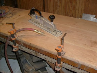
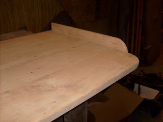
After the glue had cured, I flattened the panel with my air sander using 80 grit paper. My next step was to go over the panel with a DA sander a few times, finishing up with 220 grit. I rounded over the outside edge of the panel, and applied a fiddle to the starboard side. I put a fiddle on this edge since anything that can roll this direction has a good chance of landing in the bilge underneath the engine. Retrieving things from this area would be a pain so I'm trying to head things off with the fiddle.

I'm putting a satin finish on the work bench just to help it stay a little clean. I've never had a finish on a work bench as most of my work benches are steel. I want a wood surface on the boat so I'm not limited as to what I can do at the bench. Steel benches and wood working tools don't mix so well, so wood makes the most sense.

Installing the bench against #9 bulkhead was about as straight forward as one can get. I did have to mess around with the height of my stool/bench combination. The height of the bench came to 33", and the height of the stool will be 23". This is a comfortable height and allows me to sit upright while not hitting my my head on frame #10. I screwed cleats to the fuel tank and #9 bulkhead to support the bench and also fabricated a leg out of stainless steel tube. If the need arises, the bench will be very easy to remove and replace.

I bought a 5" vise to install on the bench, but after sitting the vice on the bench I was not happy with it. The vice dominated the bench, and just plain took up too much room. A smaller vice would not be the answer, as I hate being limited by having too small a vice for such an important tool. A vice is one of my most used tools in my shop, and I want one on my boat. I compromised with myself, and found another location. Aft of the bench where the sole steps up will actually become a good location for the vice. I can sit comfortably on the step and work at the vice. I'm not as limited to the size of work as I would have been in the work bench corner. I can also remove the sole on the step below the vice and pick up another 10" of depth if need be. I"ll have to remove the sole around the vice, reinforce things, then re install a dedicated piece of sole that the vice bolts through. By doing this, I can leave the vice bolted in place and remove pieces of sole to a gain access under the sole for maintenance and future work.

Even though the bench is not as large as I'm used too, it's going to be nice having a work bench on my boat.

Monday, April 5, 2010

Engine room sole

The engine room sole is sheathed with 1/4" aluminum diamond plate.

I was planning on using plywood for the sole due to cost concerns on my part, but having found this plate at the scrap yard has allowed me to go with, what I consider, a more attractive sole. Because of being in the engine room, and also I believe it could be a common event to have to lift pieces of the sole off for maintenance I bolted wood firing to my steel framing and then attach the aluminum sheathing to the wood. If I had screwed the aluminum sheathing directly to the steel I had visions in the not to distant future of broken screws, corrosion where screws penetrated the steel, and just more difficult maintenance in general. Having wood to screw the aluminum in to will also give me a little vibration dampening in my opinion. I'm using #12 x 1.50" stainless steel wood screws that I'm countersinking as my fastener. The sole is complete as I write this post, and to date, I've used 150 of the stainless screws to fasten the aluminum down.

I wanted as much level area in the engine room as I could build, so I stepped the sole framing up as the sole moves aft in the engine room. These steps, while some might not like, give me places of access underneath the sole, and also give me a place to sit while I'm in the engine room. Whenever I give friends tours of the progress, almost everyone sits on one of these steps. This picture to the left shows the platform I built for my tool box, and my hydraulic system reservoir.

I think the largest piece of material I've used for the engine room sole is a finished cut piece of 24"x 24". I don't want to be having to man handle large pieces when I'm I have to access under the sole. I would rather be able to lift smaller pieces, to gain access and still be kneeling or sitting on the level sole. The down side to having all these smaller pieces is I used quite a few screws.

I'm getting a pretty good feel on how the engine room is going to layout and I think I've found locations for the various equipment I'm going to need. I'm going to dedicate the port side of the room up against the main bulkhead at frame #9 as my area for my work bench. While the head room is around 5"4" in this area, I'll be able to use a short stool with a lower work bench to be able to work in a comfortable position. I'll post more about the engine room as a whole once I begin to install the various components.

The last piece of the sole for me to build is the area over the stuffing box. I'm almost out of aluminum plate so I have to give it some thought on how I want to treat this area so I don't waste any material. I think I'm going to hinge a part of this area so I can gain quick access to the stuffing box for maintenance, daily checks for leaks, and stuffing box temperature.

I have 4' 10" of head room on the starboard side of the engine, and 5' 2" on the port side of the engine. I have more headroom on the port side by my design as I knew this area would house my work bench. I'd love to have a stand up engine room, but on a boat my size, I think that would be almost impossible. I think once you get into the 50' range, stand up engine rooms start to appear. I'm totally happy with the size of the engine room, and very pleased with the head room I do have. I'll be able to easily do all my maintenance work in this space in comfort.

The scrap yard aluminum worked out great. There are some blemishes, and some cleaning that will have to be done. I know as construction progresses, the dings I put in the sole, will blend in to what was there. I'll probably never do much more than clean up the mess's I make. I have to say that I love the way the engine room is shaping up.

Thursday, April 1, 2010

Sound Proofing the engine room


The engine room received one more coating of paint on the hull and sole framing last weekend in preparation for starting the sound proofing. Well, I hope it's sound proofing, as it will be a real pain in the ass to re do this once the boat is launched.

My system for sound proofing is pretty basic. I foamed the metal ( see the last post), and now I'm attaching a 1" thick mineral wool board the the framing. Over this mineral wool I'll attach a perforated aluminum sheet as my finished wall material.

As best as I've learned, the idea behind sound dampening is to decouple the structure from the sound. Sound travels in waves and the idea behind getting rid of it is to try to absorb it. My system is to provide a barrier between the living space's and the engine room noise. My thoughts are that the sound will pass through the perforated aluminum then be absorbed by the mineral wool board and also by the foam underneath.

The mineral wool I'm getting is discarded seconds that came out of a large sheet metal fabrication shop. I'd love to have 3' x 5' boards, but I'm only able to get 2'x4' boards ( the price is right though). Because I'm not able to pick my size, I'm having to adjust my framing. In the areas I know I'm going to have to attache lots of conduits, or other mechanical items, I'm first installing plywood before installing the rock wool board. With the plywood on the hull framing ( 1/2" ply ), I don't have to worry about the rock wool laying out to hit the framing so there is almost no waste of the rock wool. I also have unlimited points of attachment for my future mechanical installations. For the ceiling though, I'm going to have to add a firing strip so the rock wool waste is minimized while I keep an eye on the weight I'm adding.

I've got a little of the product up and on the walls and part of the ceiling. I'm working in the corner where the generator will be installed, and I'm amazed at how well the sound seems to be vanishing from just having that small area installed. It's no longer necessary to wear ear plugs while working in the hull. The only drawback is that the engine room is starting to get hot from the heat from the lights.

The perforated aluminum looks fantastic and gives me just the gear head look I want for my engine room. Once the material is screwed to the wall, it stiffens up nicely. You have to look closely to see the rock wool underneath, so I feel good about the ability of the perforations to contain the rock wool while also letting the sound waves into the dampening zone. The open area of the perforated sheathing is 34%. I picked up some advice from the good posters at Metalboatbuilding.org on how the cut the stuff. It's so nice to be able to start seeing some finishing material finally going on.

Because the rock wool is 1" thick I'm going to have to fabricate some corner pieces or trim some areas out with aluminum angle. One of these areas is by the doors as you can see from this picture. I'm leaning towards angle in some areas, while in other areas, I'm going to try to brake ( bend a corner) the material in to an outside or inside corner.

I took a crack at bending some material into a corner, and it worked out OK. Having corner pieces makes the job look much more finished and I don't have to be as particular on the fit.


I had to add firing strips to the main area of the engine room ceiling. While I hate to loose another 3/4" of head room, I'm willing to take the trade as this allows my rock wool to go up with less waste. The frames for the boat are 30" on center, and my rock wool sheets are 24" x 48". I don't have the choice of 3' x 5' sheets so I added the firing strip to make things work better and get the most bang for my buck in regard to how much rock wool I have to buy.

I started out cutting the perforated aluminum with snips, but I've now switched over to my table saw. I added a board to the saws' fence so the 16 gauge material will not slide under the fence. The table saw does an excellent job of cutting the material and it looks like it was done on a shear.

You might have noticed I have some plywood installed under the rock wool. I have plywood over the fuel tanks to protect the paint job on the tank and also to give me a way to easily attach engine room components to the tanks. I plan for some cabinetry and shelving, among other things, to be installed on top of the tanks. The forward and aft water tight bulkheads also received 1/2" plywood. I installed plywood on the aft bulkhead due to the idea that my generator will sit on the starboard side, and my fuel transfer/polish manifolds and pumps will be on the port side. I don't know the exact layout of any of these components, so I put the plywood up to make it easier to attach the various bits and pieces of each system. I went with plywood on the forward bulkhead as this is the area where my work bench will be, and I want don't want to be limited to the bulkhead framing as the only points of attachment for various things.

I cut it a little close on my measurements for my fuel tank fill points. I wanted the fill lines to be as close to the outside hull sides as possible, and as you can see I achieved that. I had to hog out a bit of the rock wool, then push the aluminum in to get the two inch nipple to thread in. The rest of the assembly will fit just fine as the hull is leaning outboard at this area of the boat.

I'm pretty happy how the material bends and the fact that I'm able to fabricate some of the corner pieces I need. This picture is where the ceiling jumps up to accommodate my door. This detail is the same on both the forward and aft sections of the engine room. This detail also gives me three more inches of headroom over my work bench.

The room is about 70% complete in regard to fitting out the aluminum wall and ceiling sheathing, and 100% finished regarding the sole, so I decide to drop in the generator. The engine room is now completely closed off. I'm going to miss that large opening as it was easy to drop material into the space, and it also made things nice in regard to ventilation.

The engine room, for the most part, is sheathed. I still have to cover the seams with some trim, but I've yet to find a source or figured out what the trim will look like. I'm thinking I"ll go with a 1" piece with some sort of slight brake on both edges.